Results
MOF Samples Results
The concentrations for P, Se, Ni, and Co determined via ICP-MS were used to calculate the moles of each element (Table 7). Then the molar ratios of interest were taken to determine if the expected ratios were achieved—1:1 for P: Se, 3:2 for metal:Se or P, and 1:1 Ni:Co for samples containing both Ni and Co. For Ni-Se101, Co-Se101, and Ni-Co-Se101 the P:Se ratios were each nearly 1:1 as anticipated (Table 8). Ni-Co-Se101 had the lowest P:Se molar ratio at 0.8639. The P:Se ratio is likely lower for Ni-Co-Se101 as it experienced an additional synthetic step for the incorporation of two metals instead of one. Nevertheless, replicates will be performed in the future to confirm this lower P:Se ratio is a result of synthesis and not sample preparation steps for ICP-MS. The metal:Se ratios for Ni-Se101, Co-Se101, and Ni-Co-Se101 were ~0.3 off from the anticipated ratio of 1.5. For the metal:P ratios of all the MOFs, deviation of ~0.3-0.6 were observed. For the Se-containing set of MOFs and the S-containing set of MOFs, the single-metal containing MOFs share very similar metal:P values at 1.886 and 1.845 for Ni-Se101 and Co-Se101, respectively, and 2.114 for both Ni-S101 and Co-S101. Only the bimetallic MOFs deviated in the metal:P ratio for each MOF, which, again, is possibly due to the additional synthesis step for the incorporation of two metals. The bimetallic MOFs had Ni:Co ratios of 1.300 and 1.344 for Ni-Co-Se101 and Ni-Co-S101, respectively. These molar ratios are very close to the predicted ratio of 1:1. Given molar ratios are near expected values, the method was considered a success for quantifying the composition of the MOFs. A 100% match was not anticipated with expected values as these expected values assume perfect MOF synthesis, which is unlikely. To further confirm the composition of the MOFs, acid digestion will be carried out two more times for each MOF and ICP-MS analysis performed in the future.
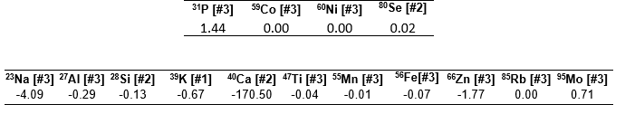
The determined concentrations from ICP-MS used to determine these molar ratios were deemed representative of the MOFs themselves as the MOF method blank had signals below the limit of the instrument for Ni and Co. Additionally, the signals for 31P and 80Se in the MOF blank were below the LOD for 31P and 80Se (see Table 9). The concentrations for Co-S101 and Ni-Co-S101 are also considered accurate despite going through a filtration step during sample preparation as the Ni:Co ratio is only 3.32% different from that of Ni-Co-Se101 and both MOFs were synthesized using the same method. Thus, precipitate formation most likely occurred during Co-S101 and Ni-Co-S101 sample digestion with elements other than those within the MOF. This precipitate formation was also observed visually when reattempting the acid digestion of these two MOFs as no particulates were observed in solution after 15 minutes only for particulates to appear after ~45 minutes. We hypothesis that this precipitate could be AgCl due to the presence of trace levels of Ag or Cl introduced via the synthesis and/or acid digestion process. To confirm this hypothesis, m/z values for Ag will be investigated in the future for all MOFs and the MOF method blank.
Table 7. MOF Element Concentrations and Moles
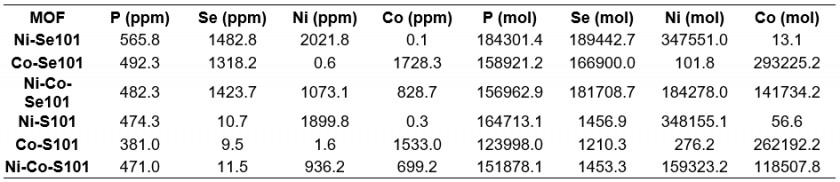
Table 8. MOF Molar Ratios
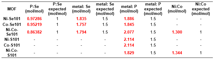
Table 9. MOF Blank (all values are in ppb)
KOH Electrolyte Analysis
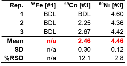
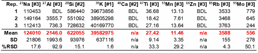
In the Fe-free KOH samples, Fe went undetected as expected. However, other elements were detected that could potentially contribute to electrocatalytic performance enhancement via unwanted incorporation into the crystalline material, such as Ni or Mo. The Ni concentration was higher in the Fe-purified KOH than the unpurified KOH, which is likely a result of the analyte used for Fe-purification, Ni nitrate, which comes into contact with the KOH solution. The concentration of Mo in the purified KOH was highly variable with a %RSD of 60.3% (Table 10). This imprecision is likely the result of Mo concentrations being below the LOD of the method. Thus, whether Mo is present cannot be truly determined. Interestingly, like the purified KOH, Fe also goes undetected in the unpurified KOH, which calls into question previous reports in the literature on Fe incorporation into electrocatalytic materials due to KOH impurities. The results in Tables 10 and 11 also indicate that Mo concentration and Ti concentrations decrease following purification, however, the diluted concentrations for these elements are near or below the LOD (see Table 4 in The Method section), meaning conclusions cannot be drawn in regard to the true successfulness of the purification process with any degree of confidence.
Table 10. Purified KOH electrolyte composition results
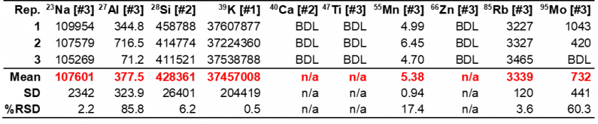
Table 11. Unpurified KOH electrolyte composition results
NiFe Dissolution Analysis
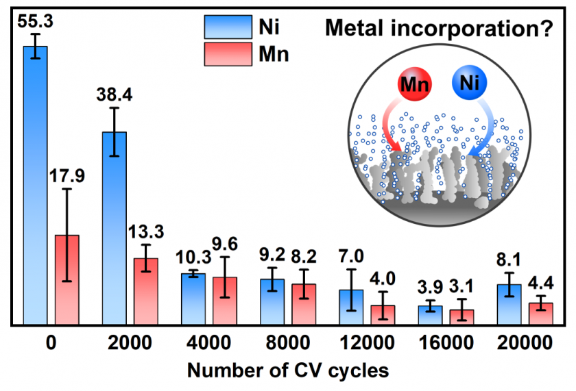
ICP-MS results displayed in Figure 7 indicate that the concentration of Ni and Mn decreased in the KOH electrolyte with increased cycling of the NiFe electrocatalyst. Given the Ni concentration in purified KOH electrolyte was ~ 14 ppb, which the electrocatalyst was initially immersed in, the Ni concentration at 0 cycles, 55.3 ppb, implies that there is an initial dissolution of Ni into the electrolyte. Then, as the number of cycles increased to 16,000, the concentration of Ni also decreased, implying re-adsorption of Ni into or onto the surface of the Ni-based electrocatalyst. At 20,000, the Ni concentration increased, signifying a transformation of the electrocatalyst’s surface due to the dissolution of Ni from itself upon contact with KOH electrolyte and re-adsorption of Ni from itself as well as the KOH electrolyte. Mn follows the same trend, implying that it too may incorporate into the electrocatalyst and possibly leaves the electrocatalyst after a given number of cycles. Given Mn was not used to prepare the electrocatalyst, the Mn detected is likely an impurity from the KOH reagent. These results are in accordance with previous metal incorporation studies,8,24 where an equilibrium is established between transition metals in the solid material and ions dissolved in the electrolyte. Hence, metal dissolution and re-adsorption might occur during cycling until a stable electrode surface is attained, which is of great importance for the design of durable commercial electrodes for alkaline water electrolysis.
Concluding Remarks and Future Outlooks
Our method for the analysis of the elemental composition of MOFs and the detection of elements evolved during electrocatalytic processes in KOH electrolyte was determined to be robust, precise, and accurate. Quality control and spike samples obtained high recoveries at or below 10%. Unknown element concentrations were within range of the calibration curves and above the PQL, with the exception of elements evaluated to gauge contamination from the sample collection and preparation processes. In addition, internal standard drift did not occur outside of acceptable ranges. Thus, elements of interest were detected quantitatively with high accuracy and glassware/equipment for sample preparation did not compromise the results of this work.
In using this ICP-MS method, MOF elemental compositions were confirmed and matched well with predictions. It was also found that a metal dissolution-incorporation equilibrium occurs at electrocatalysts’ surfaces subjected to prolonged exposure/cycling in KOH electrolyte rather than anticipated metal dissolution, which evokes additional questions in regard to electrocatalyst surface stabilization in KOH electrolyte.
Analysis of purified and unpurified KOH electrolyte samples also implies that Fe is not a major impurity in KOH as suggested in the literature, and that other impurities have negligible effects on the electrocatalytic performance. However, in the future, we plan to decrease the dilution factor for KOH samples to more confidently confirm that Fe is not present given detected Fe concentrations were below the LOD.
Nevertheless, this method demonstrates that diluting the sample with 2% HNO3 and UHP water can effectively be used to analyze KOH electrolyte samples without compromising the ICP-MS instrument and requiring additional accessories, such as the Ar dilution kit used by Patidar et al.26
In the future, we hope to investigate the dissolution-incorporation relationship of other species that have been detected during cycling of water splitting electrocatalysts, including as selenates (SeOx), tellurates (TeOx), and borates (BOx).17,20 Specifically, this work will be done in regard to the MOF samples as they will be pyrolyzed to form electrocatalysts for use in KOH electrolyte. The elemental composition of the MOFs will be determined after pyrolysis and compared to the results of this work. Then, samples of KOH exposed to the pyrolyzed (electrocatalytically active) MOFs will be evaluated as performed for the Ni-based electrocatalysts in the present work. Granted Ni, Co, Se, and P are present in the KOH MOF samples, the dissolution of material will be quantified via comparison to the elemental composition of the pyrolyzed MOFs (electrocatalysts) determined previously. In addition, we also want to study in more detail the Ni-Fe-Mn incorporation/re-absorption that has been reported for some electrocatalytic materials to clarify how the equilibrium is established, and which variables control this process. Ultimately, understanding these processes will improve the design and fabrication of robust and durable materials for electrochemical applications.