Lab Improvements & Method Development
DEVELOPMENTS FOR NWR193-FX LASER SYSTEM (2014-present)
LASER REJUVENATION
In November 2014 we had our excimer laser engine refurbished after logging more than 103 million shots.
UPGRADE TO NWR193-FX PLATFORM
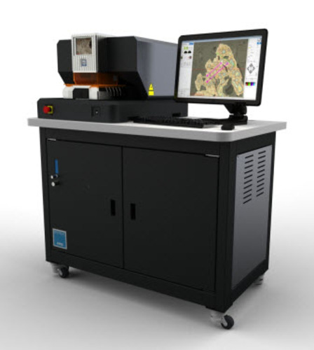
In April 2014 we upgraded our laser ablation system to the ESI New Wave Research’s NWR optical platform. This system provides significant improvements in analytical capabilities. New features include:
- Ability to work with layered imagery (e.g., SEM, EPMA, CL, UV Fluorescence), allowing user to efficiently optimize laser spot/scan positions.
- Touch screen monitor for rapid movement to areas of the ablation chamber.
- Software-controlled apertures (IVA – infinitely variable apertures) allowing spot diameters to be customized within 1 µm.
- Software-controlled rotational XY shutter (XYR), allowing rectangular slits to be customized, and rotated in-run for curvilinear transects (e.g., to minimize time-series aliasing in growth banded/zoned materials.
- Laser log files for 2D/3D chemical mapping in laser ablation data analysis software.
~~~~~~~~~~~~~~~~~~~~~~~~~~~~~~~~~~~~~~~~~~~~~~~~~~~~~~~~~~~~~~~~~~~~~~~~~~~~~~~~~~~~~~~~~~~~~~~~~~
DEVELOPMENTS FOR UP193-FX LASER SYSTEM (2009-2014)
Addition of Rectangular “Spots” to UP-193-FX Laser
We have added a customized aperture wheel that, in addition to conventional spots, includes four rectangular slit options: 5 x 50µm, 5 x 150µm, 10 x 100µm, and 25 x 150µm. The slit options offer substantially better spatial/temporal resolution compared to spots for solid phases that have unidirectional compositional variations (i.e., speleothems, zoned cements). Slit orientations are vertical only, so samples must be rotated within the laser cell such that growth band axes are also vertical. See Laser Mode page for more information.

 Addition of Liquid Argon Manifold
Liquid argon is one of the largest operational costs associated with ICP-MS labs. Liquid argon dewars continuously vent, whether used or not, and built-in tank pressure gauges are often very inaccurate (i.e., tanks reading 1/3 full have gone empty before). As a precaution, when 230 lb dewars seemed “light” (as judged by physically rocking the dewar) they were considered too unreliable to risk further use and possible critical loss of Ar pressure, and a new tank was installed. An estimated 10-20% of liquid Ar was wasted by this practice.
To stop this loss, we have installed a manifold system that enables on-line switching and replacement of Ar tanks. The system should pay for itself within one year of normal operation, thereafter recouping 10-20% Ar savings.
 |
 |
Testing and Purchase of a Large Format Laser Ablation Cell
.")
Traditional laser ablation cells tend to have relatively small sample chambers, optimized for standard thin-sections and 1” probe rounds. These geometric constraints can be problematic and contribute to inefficiency in laser ablation projects. For example, slit apertures require samples to be oriented such that growth/accretion axes of unknowns are vertical (parallel to the slit long axis). Optimal positioning of such samples may not be possible using standard laser cells. In addition, sample sizes may prohibit the simultaneous inclusion of one or more laser ablation standards. This means that samples and standards must be switched out, requiring venting, and time-intensive redetermination of xyz coordinates.
 offers fast washout by limiting the cell volume and imposing laminar flow across the sample surface.")
A large format laser cell potentially overcomes many of the drawbacks of standard cells, and additionally offers faster washout times. In many cases an entire study (samples and ablation standards) can be placed in the chamber at one time. Xyz coordinates need only to be optimized once in the analytical session, and analyses of unknowns and standards are then fully automated for greater efficiency. To evaluate the potential merits of a LFC, we tested a demo model from ESI/New Wave Research. Downsides to this LFC are that it precludes transmitted light, and is not easily installed/removed. After testing, however, these issues proved to be minor and the overwhelming benefits of this system ultimately facilitated a successful funding initiative within JSG.
So . . . Is the LFC flexible with sample numbers and orientations? Yes, this was demonstrated repeatedly for several diverse projects (examples of loaded LFC drawers below).

So . . . Does the LFC really offer faster washout?
Yes, due to the more efficient collection of the ablation plume locally just above the ablation site, as opposed to more distally at or along one side of the ablation chamber (as the case for small format laser cells shown above).

Installation and Testing of a High Energy Optical Attenuator
In LA-ICP-MS, solid materials are “digested” by a laser beam and carried by an inert gas to the plasma of the ICP-MS. RSDs and detection limits are higher than solution mode ICP-MS due to greater variations in the particulate aerosol flux passing through the plasma. Consistent optimized ablation is the key to lowering RSDS, and this argument establishes the case for installation of a high-energy attenuator to control laser pulse-to-pulse energies delivered to the sample surface.
The Problem
The NewWave UP-193 fx laser system uses an ATL Lasertechnik Atlex SI excimer laser. Energy stability of excimer lasers is lowest at low power, which is the power range over which we do most work on geologic samples (typically 20-40% laser power). The best energy stability is obtained at the maximum high voltage, which on the ATL Atlex SI (16kV) is 3% (one std dev). Technically, setting the laser power over the working range corresponds to the thyratron voltage range used to control beam energies. At low voltages, the beam stability is worse than at high voltages.
So how variable is the ATL excimer stability at low power?

So what? What are the cons of low lower laser instability?
The issue is not one of stoichiometric ablation of elements into the aerosol, but rather what happens when the stream of particles that reaches the plasma is not consistent. At any given time if the carrier stream is carrying a low number of particles (e.g. from a low energy pulse), then the annihilation of those particles in the plasma will be highly efficient. If a larger number of particles is delivered to the plasma (from a higher energy ablation), then there is both (1) a quenching effect that temporarily reduces the temperature of the plasma, and (2) a lower efficiency of particle annihilation. When the efficiency of particle annihilation changes in the plasma, the ionization of each element, and therefore what reaches the detector, changes.
Example Simulation of this Effect
Tune ICP-MS to give a 232Th/238U ratio of 1 for an ablation of NIST 612 with a 100µm spot. Change the spot to a smaller size (10-15µm) and keep all the other parameters the same. The measured ratio now changes, due to changes in the amount of material passing through the plasma.
There are two ways to improve the consistency of the particle stream arriving at the ICP.
- A mixing chamber/squid device can be used to mix the carrier stream, however this has negatives such as wash-in and wash-out are greatly extended, signal intensity can be reduced, and the device often contributes a form of fractionation.
- Ensure that each ablation is of a similar particle size range and density. This requires that the same energy (fluence) arrives at the sample on each pulse. The more stable the laser, the better the particle size distribution. The high energy attenuator is designed to do just this at lower energy – take a stable starting laser at a higher energy and optically attenuate it.

How does the high energy attenuator work?
The attenuator optic is a planar material that varies transmission based on the incidence angle of the laser beam to the optic. As the optic is moved relative to the beam, the transmission varies relative to the sine function of the angle of incidence. The greatest attenuation occurs when the optic in perpendicular to the beam (as shown to the right). Less attenuation occurs as the optics are rotated to higher angles. The attenuator does not alter the beam profile or shape in any way; it just partially transmits the beam.
The attenuator works in three modes in order to preserve high stability and linearity from 0-100% energy (see graphic below-right).
MODE 1 (for working at lowest energies): Laser output energy is fixed at a stable minimum energy of 5mJ. The attenuator optic is then adjusted to vary the energy accordingly.
MODE 2 (for working at mid-to-high energies): The attenuator optic is fixed at the maximum energy position (highest angle setting), while the laser output energy is ramped.
MODE 3 (for working at highest energies): The optic attenuator is rotated completely out of the beam path, while laser output is adjusted from 5mJ to 8mJ.
 |
 |
Graphic courtesy of ESI/NewWave Research
The UT Austin Attenuator – Does it work?
Final calibration of the attenuator for the UT Austin optical attenuator is shown in the plot to the right. To test the new laser output stability over the common range of low power laser energies appropriate for geologic samples, relative % variance was evaluated for a 50µm spot at 10 Hz. The table below demonstrates that variation in Fluence and Irradiance is now consistently below 3% at energies at and below 40% laser power.

The relative improvement that the attenuator provides can evaluated by looking at historical records of pre-attenuator laser output for analyses performed over a range of laser powers, as shown below.


This comparison indicates that laser output stability can be expected to improve by a factor of 4 for work at 15% laser energy, 3.4 for work at 20% laser energy, 2.5 for 30% laser energy, and 1.3 for work at 40% laser energy. High laser output stability for work below 15% power is now practical.