JEOL 8200 Electron Microprobe (EPMA)
Location
JGB5.106a
Overview
The JEOL JXA-8200 Electron Microprobe (EPMA) was installed in 2002-2003.
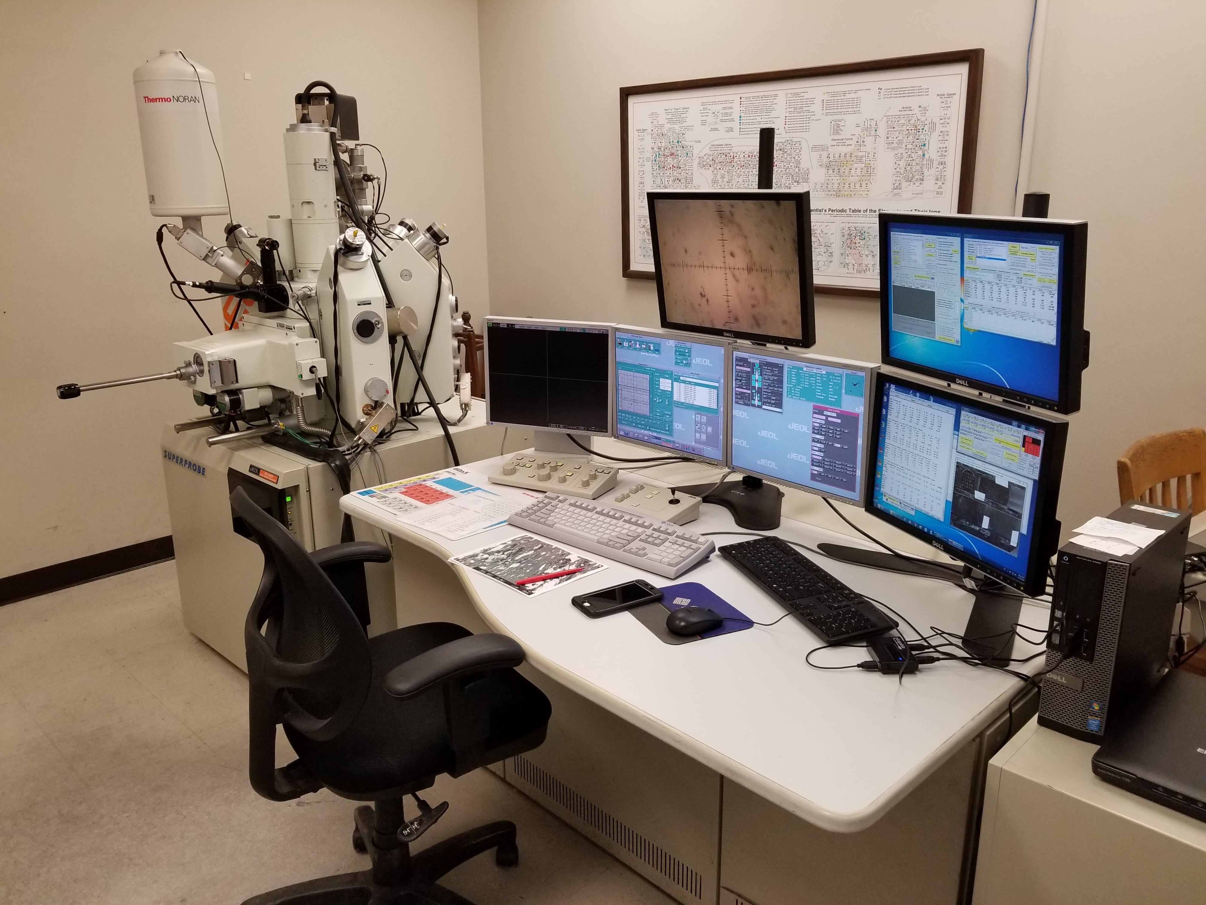
The JEOL JXA-8200 at the DGS GeoMatCI is equipped with:
- 5 wavelength dispersive spectrometers (WDS)
- Secondary Electron (SE) and Back-Scattered Electron (BSE) detectors
- Probe for EPMA software for state-of-the-art quantification and automated analyses.
The primary purpose of the electron microprobe is to generate quantitative and qualitative chemical analyses of any material that is stable under the electron beam and under a high vacuum. Such materials include minerals, glasses, ceramics, and metals/alloys.
What’s the difference between an SEM and an EPMA?
The SEM and EPMA are very similar instruments. Both produce electron images and x-ray intensity data (via EDS or WDS detectors). The microprobe is essentially a highly specialized SEM focused entirely on high accuracy and high precision X-ray analysis at the cost of the flexibility in sample type offered by an SEM.
Compared to EDS detectors, the WDS system offers better peak-to-background X-ray intensities and the ability to resolve X-rays whose energies, and wavelengths, are very similar (e.g. Ba and Ti). Therefore, the EPMA is best suited for the accurate and precise measurement of elements at trace (>100 ppm) concentrations or with very high Z (i.e. lanthanides and actinides). Because the microprobe has 5 separate WDS spectrometers, analysis of 10 elements to 100s of ppm precision can be performed in just a few minutes.
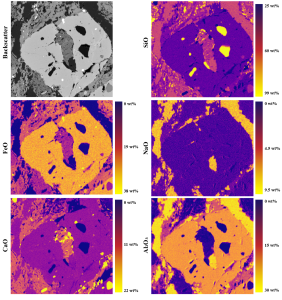
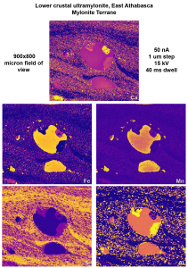
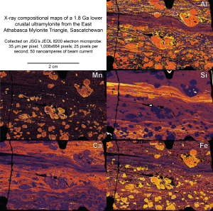
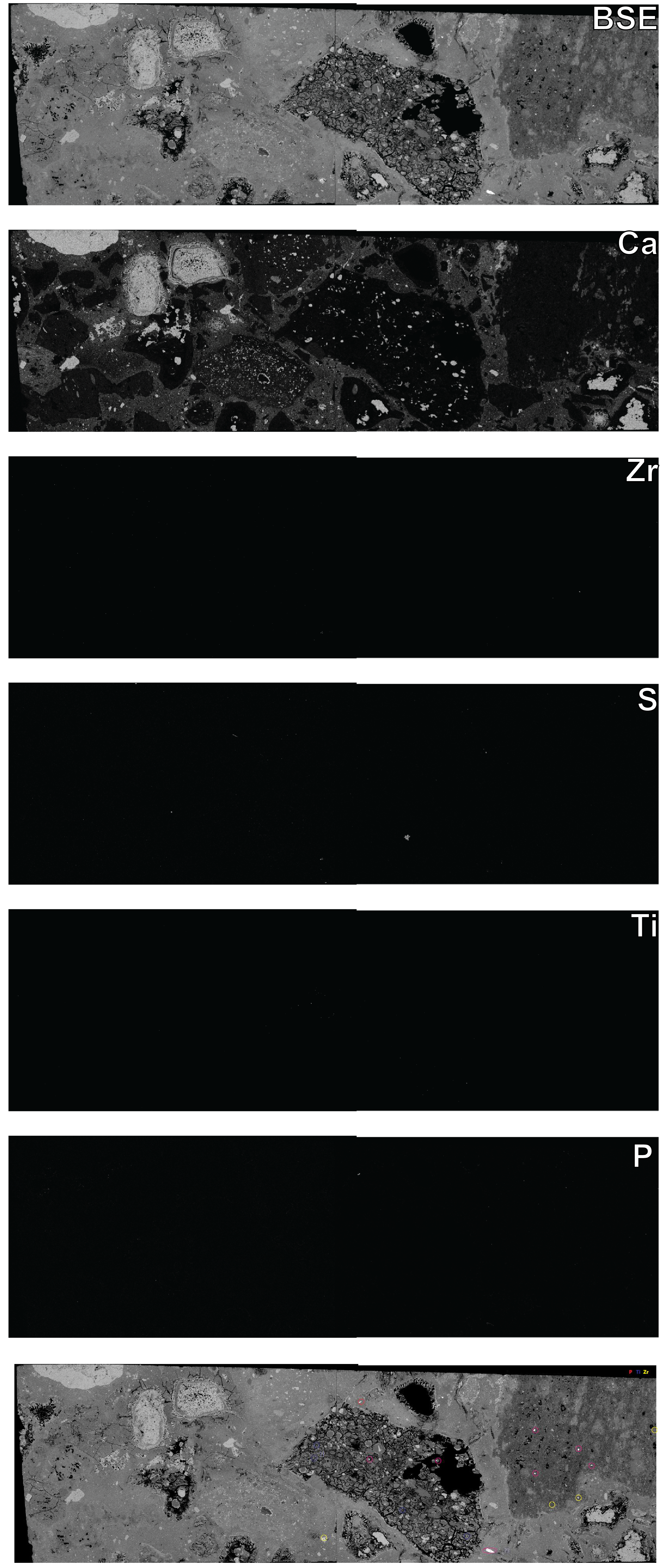
Like an EDS-equipped SEM, the microprobe’s WDS spectrometers can be tuned to specific elements and used to create X-ray element maps of samples on micron to cm scales. The microprobe beam can be de-focused into diameters ranging from 0.7 to 50 microns, which can allow matching of mapping step size for efficient large-area mapping. All X-ray maps can also be quantified with a simple standardization process, with precision dependent on pixel dwell times (minimum 2 ms @ 20-micron steps).
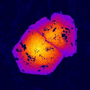
Examples
Requirements of Samples
- Samples, and their mounting media, must be stable under a high vacuum (10e-5 Pa)
- Samples must be stable under the electron beam. Temperatures in excess of 100°C to 200°C can be generated by the electron beam at the sample surface. Special analytical methods can be applied to beam-sensitive samples. Users interested in the analysis of such materials should contact the lab manager to discuss analytical goals.
- Samples must be electrically conductive and grounded to the instrument (stage). Because most geological materials are insulators, most samples require a conductive coating before imaging and analysis. We typically use carbon coats due to the high X-ray transparency of C, unlike Au.
- Samples must be flat and polished. Good polish is one important key to good results.
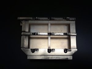
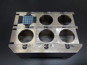
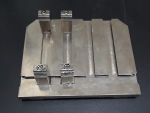
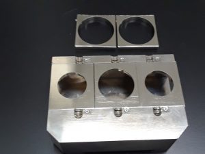
Sample Shape and Size
Common samples are standard, polished thin sections and 1″ round sections. Very thin (<3 mm) and thick (3 mm) polished slabs mounted on a standard-sized petrographic thin section can also be used. The instrument can hold a maximum of four standard thin sections, one 2×3″ thin section, six 1″ rounds, two 1.25″ round sections, OR two 1.5″ rounds. Samples can also be mounted in 0.25″ brass sleeves, which are secured in a 1″ round mount with six 0.25″ holes. Sample changes are easily accomplished by users with minimal training and take about 5 minutes.